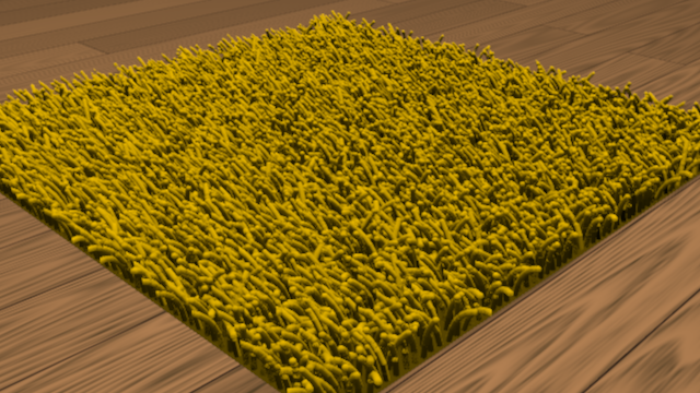
Air 12.09 introduces a new FakeCarpet surface shader that turns a simple rectangle into a patch of fuzzy carpet. The carpet effect is produced by ray tracing a virtual field of carpet fibers inside the surface shader; no additional geometry is created in the scene. This blog post provides a list of the required steps for creating fake carpet, followed by tips for tuning the shape, shading, and sampling parameters of the shader.
Getting Started
Here’s how to add carpet to a room model:
- Create a four-sided polygon and position it slightly above the floor. The polygon should represent the top of the area to be covered by the carpet. Make the polygon invisible to shadow rays.
- Assign the FakeCarpet surface shader. You will probably want to disable the material preview window in your application when tuning this shader because the preview render can take a long time.
- Set the SizeX and SizeY parameters to the width and length of the carpet rectangle. SizeX gives the size along the first texture coordinate axis, SizeY the size along the second texture coordinate axis.
- Set StrandLength to the length of the carpet fibers, which should be less than or equal to the height of the polygon above the floor.
That completes the the required steps to use the FakeCarpet shader. You should then be able to render a test image of your scene and see some carpet.
Carpet Shape
The carpet is modeled as a grid of carpet fibers. The geometric model of the fibers can be tuned using the following parameters:
StrandCount, StrandWidthFraction
The overall density of the fibers is set with StrandCount, which gives the number of fibers per unit length. The diameter of a fiber is given by the StrandWidthFraction parameter as a fraction of the fiber length.
StrandTiltAngle, StrandTiltVary, StrandTiltFrequency, StrandStiffness
StrandPolarAngle, StrandPolarVary, StrandPolarFrequency
Individual fibers are represented as curved tubes. StrandTiltAngle gives the average angle (in degrees) between the vertical direction and the tip of a fiber. The tilt angle can be varied for each fiber using StrandTiltVary and StrandTiltFrequency. StrandTiltFrequency is relative to the entire patch of carpet. StrandStiffness controls how each fiber bends. Higher values push the curve more toward the tip of each tube.
The direction of tilt can be changed using the StrandPolar parameters, which control a rotation in degrees about the vertical axis.
StrandSegments, TraceTip, TraceJoint
Each fiber is represented as a chain of tubular line segments. StrandSegments gives the number of segments per fiber. Each segment can be capped with a sphere. TraceTip controls whether a sphere is traced at the tip of each fiber. TraceJoints controls whether spheres are traced at the joints between segments in a fiber.
Carpet Shading
The carpet is shaded using an empirical model that assumes some light is reflected from the front of each fiber and some is transmitted.
FrontScatter, BackScatter, ScatterPower
FrontScatter gives the fraction of light reflected from the front of a fiber. BackScatter gives the amount transmitted from behind. Both are modulated based on the angle between the shading normal and the view direction such that more light is transmitted along the fiber edges and less in the middle. The ScatterPower parameter is an exponent applied to the angle cosine used for this edge-based variation.
SelfShadowMax, ColorMapName, BaseColor, IndirectDiffuse
SelfShadowMax gives the maximum self-shadowing of the carpet (the shadowing effect of neighboring fibers). Self-shadowing is greatest at the base of each fiber and smoothly attenuates to zero at the tip.
ColorMapName allows a color map to be applied to the fibers.
BaseColor gives the color of the “fabric” under the fibers, which is visible where fibers are missing.
IndirectDiffuse is a simple multiplier for the diffuse result returned for indirect illumination. The shader does not trace fibers for indirect rays.
Carpet Trace Controls
The FakeCarpet shader performs ray tracing to determine which fibers are visible at each shading location. The following parameters control this internal ray tracing process:
SampleGridSize
Because the carpet fibers will typically be much smaller than a pixel, the shader provides an option to trace multiple rays to produce a smoother, more accurate result. SampleGridSize defines the size of an NxN grid of rays to trace at the current shading location. The grid size is automatically reduced to 1 for reflection rays and IPR (interactive preview) rendering.
TraceMargin
The FakeCarpet shader treats the rectangular polygon as a sort of window into a virtual grid of 3D fibers. There can be artifacts along the edges if this “window” clips the carpet. To help prevent those artifacts, the TraceMargin parameter strips away a fraction of the fibers along the carpet border. Larger values remove more rows of fibers.
TestForIntersections, TraceBias
TestForIntersections determines whether the shader checks for objects intersecting the carpet (such as a chair leg). If there are no objects on the carpet, set this parameter to 0 to save some time and potentially avoid some artifacts. The TraceBias parameter gives an offset used to avoid incorrect intersections in this test.
Final Remarks
The FakeCarpet surface is a fairly complicated shader, and you will likely need to experiment with the parameters to reproduce the appearance of a particular type of carpet. An IPR session (utilizing TweakAir) can be used to interactively view the effects of parameter changes.

